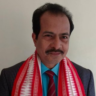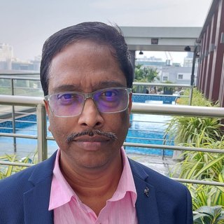
Pratyush Kumar Sahu
Idea and implementation
B.Tech, Electronics and Communication Engineering, Silicon University, Bhubaneswar (2023–2027)
Pratyush came up with the idea for VLSI_Toolkit and built it. He works on RTL design and verification in Verilog and SystemVerilog. His projects include a 5-stage pipelined RV32I processor with hazard detection and forwarding, a hybrid Radix-4/8 Booth multiplier for low-power edge AI, and RV32I core integration for the national 1-TOPS RISC-V SoC tape-out programme, where his team was selected among the top 37 of more than 550.